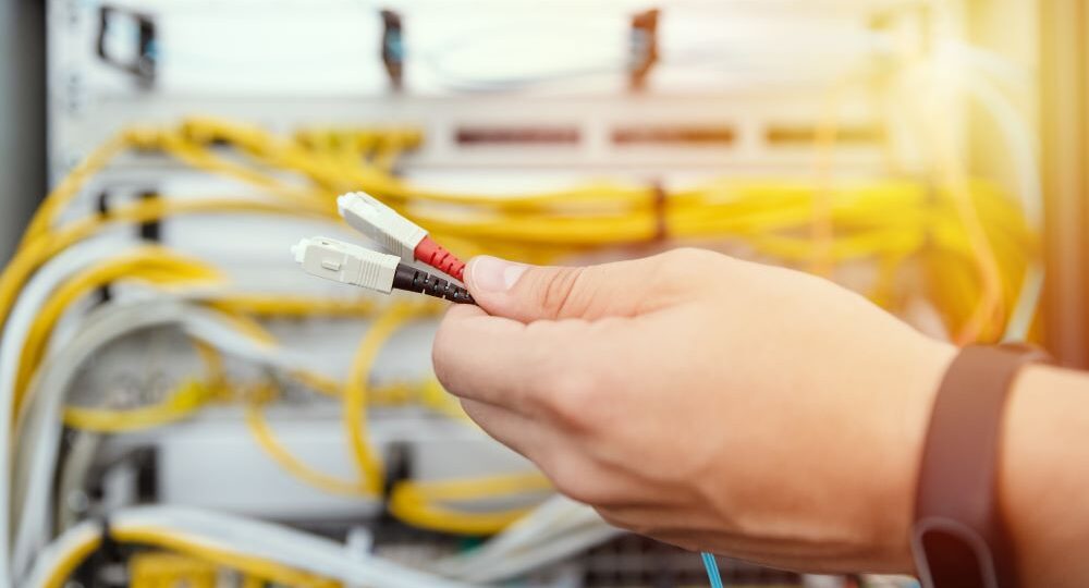
Optical connectors are the physical interface that links an optical device to a fiber optic cable.
Fiber optics are used in many applications, including medical imaging, automotive, military, industrial, and commercial (e.g., telecommunications). Each of these systems has multiple optical connectors. They’re the input and output ports for everyday interfacing with optical modules in telecommunication networks, test instruments, and any other systems that use fiber cables.
There are many different types of connectors available, each with their own pros and cons, depending on where the fiber is installed and the operating environment it is used in. The right connector depends on your application requirements, and selection will depend on several factors including type of connectors in the systems’ optical modules, environmental requirements of the fiber cable and connectors, size, weight, and cost.
Optical Connectors
Optical connectors are a critical part of any optical system. They’re the interface between the components, and they need to be reliable. For example, if you have an application where data needs to be transmitted from one place to another over an optical fiber, then you need an optical connector that can handle these signals with minimal loss or distortion. This means selecting a connector with sufficient optical coupling, good mechanical design, materials that can withstand repeated use without failing (e.g., corrosion), while maintaining performance under all anticipated operating conditions. The connectors also need to interface with the connectors and type of fiber, whether that be single mode or multimode fiber, of system’s optical modules.
Connector Types
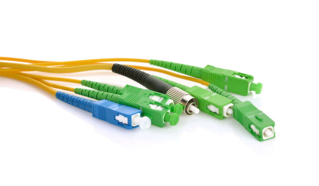
Fiber optic cable connectors generally fall into two categories: physical contact connectors and expanded beam connectors. Physical contact (PC) connectors do just that, physically bring the two fiber facets together to couple the light between the fiber cores. PC connectors are extremely common, low cost, and quite reliable when handled correctly. PC connectors are available in a variety of types, with the most common being SC, LC, ST, FC, and MPO/MTP. Though there are several other connector types and even variations on these more common connectors as well.
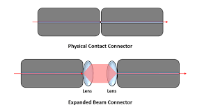
Expanded beam connectors use a lens at the interface with the signal propagating through the air and being coupled back into the mating fiber to couple the light. Expanded beam connectors are more expensive than PC connector and typically have higher coupling loss but do have the advantage of being able to withstand a high number of mating cycles since there is no physical contact between the fiber facets and are less susceptible to dust and contamination since the beam is expanded much, much greater than the size of the fiber core. Therefore, expanded beam connectors are more commonly used in highly rugged environments, such as military, outdoor energy installation, down-hole link, or cases where the fiber must undergo a high number of mating cycles, such as medical environments that undergo frequent cleaning.
Overview of Common Connector Types
There are pros and cons for all the common connectors, so let’s look at each of them individually.
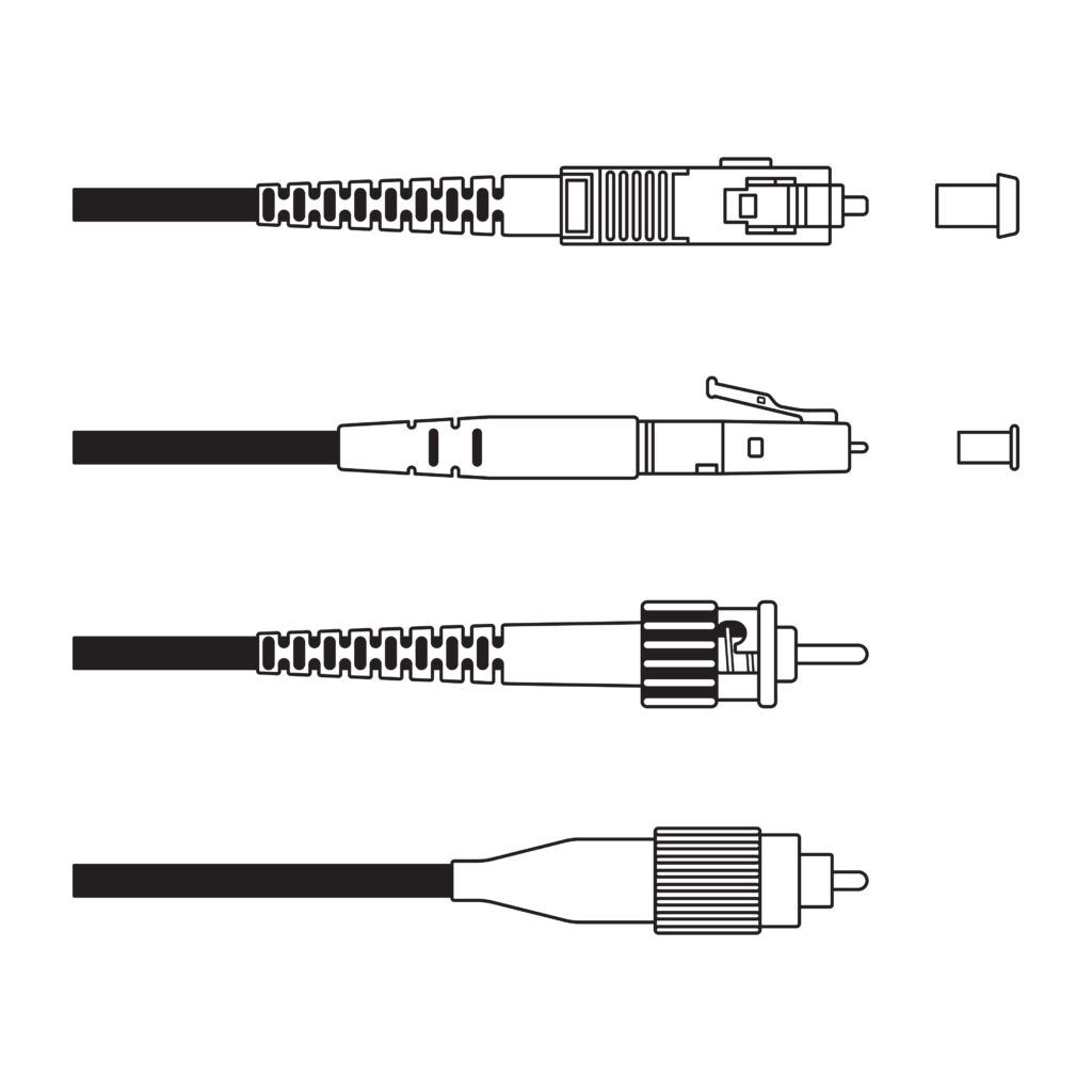
- SC (Square connector) has a 2.5mm (about 0.1 in) ferrule and attaches with a push and click mechanism. It is a robust connector that is easy to field terminate but requires a larger footprint on the device and panels.
- LC (Lucent connector) has a 1.25mm (about 0.05 in) ferrule and also attaches with a push and click mechanism. The smaller footprint makes this the connector of choice for many datacenter applications.
- ST (Straight tip) has a 2.5mm ferrule and also includes a spring-loaded mechanism in a half-twist bayonet mount for a rugged connection in many operating environments.
- FC (Ferrule connector) has a ceramic ferrule with a stainless-steel screw down connection mechanism, making it a very rugged connection for harsh environments that can tolerate the larger size.
- MTP/MPO (Multi-position parallel optic) is a multi-fiber connector that may have 4, 8, 12, or even 24 fibers in a single connector that mates with a push and click mechanism. The fibers must be precisely terminated from the ribbon cable into the connector but allows for high-density fiber ports in a very small footprint.
Other considerations when choosing a connector and fiber cable
While the connectors discussed here can all be used for either single mode or multimode fiber, it is critical to get the right fiber in the connector so that the system can transmit and receive the signals correctly without significant loss or distortion. Additionally, the loss budget can be different for single mode compared to multimode, so be sure to take that into account when choosing a connector.
Type of fiber facet polish may also be important. The physical contact may be made between a PC (physical contact), UPC (ultra physical contact), or APC (angled physical contact). Most facets these days are either UPC or APC, as processing improvements have pretty much eliminated the use of PC, which has a polished interface with a small curvature, in favor of the UPC, which has a larger curvature and improved surface polish, leading to a return loss of –50dB or better in a single mode application. APC polishing includes an 8° angle on the facet that tends to reflect light back into the cladding rather than the core, leading to a return loss of –60dB or better. Generally, APC should be mated with another for best performance.
For LC and SC connector types, there is a general color code used throughout the industry to easily differentiate between a UPC and APC facet. For UPC, the connector housing will typically be blue, and for APC, the connector housing will typically be green. This makes it easy to identify which type of fiber facet polish your connector has so that you can mate it correctly.
The best optical solution is the one that results in the most reliable interconnect
Ensuring that your optical interconnect is reliable is important, and this may even mean integrating different types of optical connectors throughout your optical link. The first requirement is that the fiber connectors interface with the optical modules themselves, so if they have an LC port, the fiber cable needs to have an LC port.
However, if the optical module has an ST port, then the fiber cable needs to have an ST connector, at least on that end of the fiber cable. The environmental requirements or system design may call for a different type of connector on the other end of the fiber cable. For example, the transmitter module may require an ST connector to interface with the optical module, but the other end may be an FC connector to pass through a panel or mate with a receiver that has a different optical connector interface.
Choosing the type of connectors in your system requires knowledge of all the types of connectors throughout the system, not just the end points. Each fiber cable must be terminated with the right connectors at each point, ensuring that the type of connector meets the requirements for temperature, shock, vibration, humidity, mate/de-mate cycles, etc.
Additionally, each connection in the system will incur some loss. It is important to know what this loss will be, both for a typical installation, and worst-case conditions, to ensure that your optical link will meet link budget requirements, which means that the optical signal quality will still be sufficient at the receiver to correctly determine the transmitted signal.
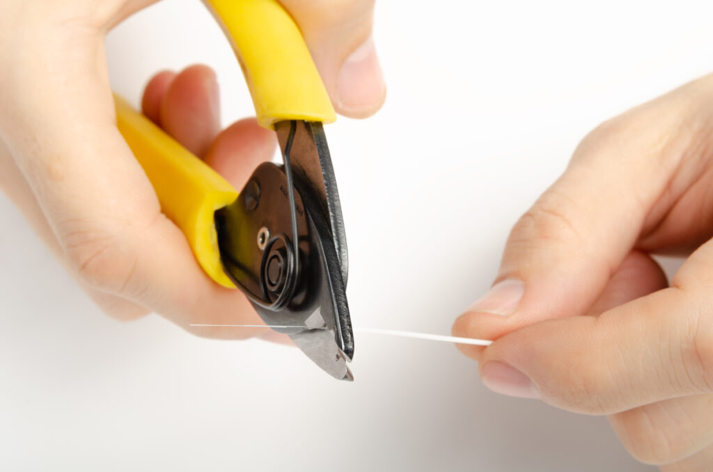
What about field termination? Is this possible with fiber connectors?
SC and LC connectors are both commonly used for field termination, and both are available with no-polish, no-epoxy quick-connect field terminations. SC connectors are the larger of the two, and some people find it somewhat easier to field terminate, just because the parts are easier to hold – Inneos adapters and extenders all use SC connectors. LC connectors are smaller and are more commonly found in Datacom applications; therefore, you will often see LC connectors if your AV equipment uses only a 10 Gbps SFP+ module for the optical link.
MTP/MPO connectors have multiple fibers that must be precisely aligned within the connector and with each other. This makes field termination of MTP/MPO connectors a less feasible option without costly equipment and highly trained technicians.
Conclusion
Optical connectors are a vital part of any optical network, as the fiber cable needs robust connections to efficiently and reliably couple light into and out of the fiber. There are many types of connectors available for different applications and environments, so it’s important that you choose the right one for your system needs. If you still have questions about the right optical connectors and components for your optical interconnect solution, our optical design experts are here to help.