A Practical Overview for Design Engineers New to Optical Interconnects
If you’re an engineer considering fiber optics for the first time — whether for high-speed data, monitoring remote sensors, or uncompressed video — the good news is: you don’t need to become a photonics expert to get started. Inneos simplifies the integration process so you can focus on your system, not your signal path.

Benefits of Fiber Optic Systems
At a high level, fiber offers some key advantages:
- Higher bandwidth at longer distances
- Immunity to EMI, crosstalk, and ground loops
- Lightweight, compact cabling — flexible, small, and rugged for easy routing
- Improved signal integrity — no equalization or re-timers required
What Changes When You Switch from Copper to Fiber?
What changes for you as a designer? Instead of running a differential signal straight to a connector, you now need:
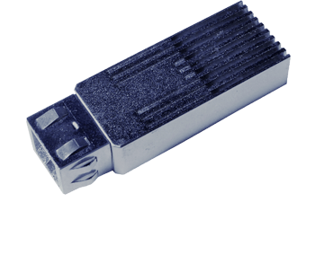
- An optical transmitter – such as a VCSEL-based optical engine
- A fiber optic link – this is the cable
- An optical receiver – typically including a photodiode + amplifier

The good news? Inneos does all of this in a fully integrated module or turnkey system — so you don’t have to design from scratch.
Key Design Choices You’ll Make
Here are the major factors to consider when adding fiber to your system:
Protocol & Signaling Considerations
Our optical subsystems are flexible enough to support a wide range of digital protocols and handle all optical conversion internally. The optical subassembly itself is protocol agnostic, so it can handle any DC-balanced protocol, though there may be other timing, signaling, and handshaking required for the full protocol-level implementation. Inneos can help with that. We have experience with Ethernet, HDMI, DisplayPort, USB, MIPI, and PCIe, and our turnkey modules support full rate, uncompressed 4K HDMI video.
System Integration
Optical engines do have some important design considerations to keep in mind — especially at high data rates. You’ll need to account for:
- Layout of high-speed traces to/from the optical module
- Thermal path to chassis or heat sink
- Vibration/shock constraints
- Connector retention and strain relief
Inneos can provide mechanical models, reference designs, and mounting guidelines to make this easy.
Power Supply and Control Interfaces
- Typical modules require 3.3V or 5V power
- I²C interface is used for diagnostics, control, and status monitoring
- Enable pins available for eye safety and power management
We can provide an integration guide with recommended power supply filtering, circuit schematics, and timing considerations.
We Have Tools to Help You Get Started
- Evaluation Kits – Test Inneos optical links with your system
- Reference Designs – PCB footprints, connector placement, thermal paths
- Mechanical CAD Models – For early enclosure and board layout planning
- Integration Support – Our engineering team can help review and advise
Where to Go From Here
Ready to integrate fiber but not sure where to start? Here’s a suggested path:
- Test a turnkey extender – See real-world fiber performance in your application
- Prototype with an embedded optical engine – Use our evaluation kit or reference design to get started
- Design in production hardware – With support from Inneos’ applications team the whole way
Fiber Doesn’t Have to Be Hard
Whether you’re building a surgical platform, embedded compute module, or AI-enabled sensor array — we’re here to help you make the transition to fiber without the headache.
At Inneos, we’ve helped many design teams successfully integrate optical links into complex systems — some with no prior fiber experience. We build rugged, high-performance solutions that are as easy to integrate as any electrical component.
You don’t need to be a photonics expert. You just need the right partner.